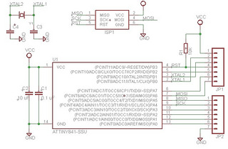
A microcontroller requires very few external components to work in an electronic circuit. The present tutorial will expose the minimum components we need to get an ATtiny841 up and running, an 8 bit microcontroller, and what is the purpose of those external elements in reference to the microcontroller.
1. The decoupling capacitor
One of the first prerequisites for a microcontroller to function is to have a voltage potential between its power supply pins, typically we will either find 5 Vdc or 3.3 Vdc in many designs involving microcontrollers. Components that a designer would have to be mindful of adding are decoupling capacitors.
Decoupling capacitor
When we study how much current a microcontroller consumes to characterize it, the figure would be the average consumption. Nonetheless, the microcontroller doesn’t drain that current constantly, instead there are high frequency current peaks in sync with the clock signal or its digital output switching on/off.
The power supply can’t cope with those high frequency current transitions to instantly source the microcontroller, and that is due to pin output and pcb track impedance that link the power supply source to the supply pins of the microcontroller. Decoupling capacitors are great to help with this.
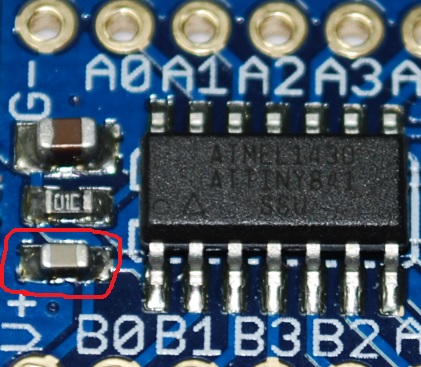
A decoupling capacitor is a small capacitor, in the order of 100 nF, which needs placing as close as possible to the microcontroller power input pins, refer to the image above. This capacitor provides the current pulses required by the microcontroller to operate, if we forget about it and leave it out our design the noise in the power lines will increase accordingly and that could affect badly to readings coming from some analog circuitry or any other malfunction caused by noise.
Therefore, we should religiously add decoupling capacitors to our integrated circuits in our pcb designs, these should be located between each pair of supply and ground pins and as close as possible to the supply pins of the integrated circuit.
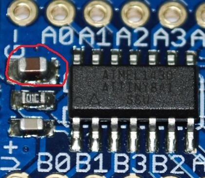
In addition to the decoupling capacitor it is also good practice to place a bulk capacitor in the board.
Bulk capacitor
This capacitor is bigger than the decoupling capacitor, at a figure around tens or hundreds of microfarads and it is convenient to add if the power supply is located out of the pcb we are designing (as power supplies typically have their own decoupling capacitors built in). The purpose is to minimize the amount of noise present in the supply lines of our electronic circuit. Its location isn’t as critical as the decoupling capacitor hence it could go anywhere in the board.
Capacitors is a topic by itself, and could be complex when there is a target impedance to achieve to minimize how much noise there is in the power supply lines. But in general terms it is good practice to always add a decoupling capacitor to any integrated circuit, and a bulk capacitor at the supply area if the power source of the board is external to the pcb.
2. Programming connector
Unless the microcontroller comes delivered with a bootloader already flashed, we always must think about the connector that will let us download our code into the microcontroller.
Programming connector
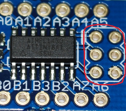
The image above shows the pads where the programming connector will be soldered and that act as a programming interface for the microcontroller.
This pads are linked to the microcontroller input and output pins (A4, A5, A6 and B3 in our case), additionally these pins could be used for a general digital input/output purpose for any other tasks.
If not only did we want to dedicate the pins for programming purposes but also for other generic usage, we should be wary of protecting the programmer from the rest of extra electronic circuitry connected to the same pins and that could interfere with the programming result.
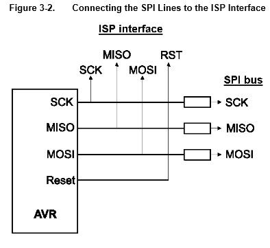
In series resistors at the programming lines
The picture above provides a graphical example for a dual usage of the programming pins: downloading software and to establish a serial communication with other devices.
The programming connector will be connected directly to the microcontroller programming pins. For instance, if during programming the SCK line drops to 0, and a device connected sets the line to 1 there will be a chance for a short circuit to happen. The way to prevent this would be to add a resistor in series to limit the current in situations described in the last example, that would result in a 0 at the SCK pin and a 1 on the SPI bus resistor end. Generally, the resistor value should be above 1K, and a mindful analysis should happen to evaluate the impact of these in series resistors to the alternative general usage.
3. Clock signal.
The programming connector and decoupling capacitors tend to be the minimal amount of components that will find as a constant in all the electronic circuits with microcontrollers. Another fundamental component for the good working of the processor is the clock source, this oscillating signal could either be generated with components embedded in the microcontroller or external and dedicated hardware instead.
The clock synchronizes all the computational operations that take place within the microcontroller, a microcontroller without a clock is totally useless. Every certain amount of clock cycles the microcontroller executes a program instruction from its memory.
In order to tell the microcontroller what its clock source would be, there are some fuses to configure, we can access them as per described in this tutorial. The fuses are bytes that reside in the microcontroller and that we can normally access through a programmer, they set how the microcontroller hardware should perform.
The microcontroller has an internal oscillator capable of generating an 8 MHz clock signal, to select it in the fuses configuration window we have to check the INTRCOSC_8MHz as depicted in the image below and click on the program button after the change.
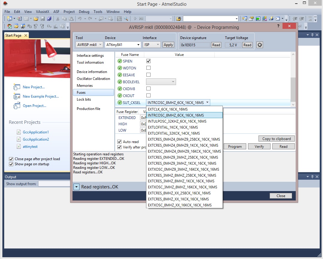
Important note: we must not select the first option, EXTCLK, if we did so we will be commanding the microcontroller with an external clock signal that will need to be connected to one of its pins. From the time we confirm that selection we won’t be able to program the microcontroller or reconfigure the fuses unless we produce a square wave signal to the corresponding clock input pin that was selected. Be very careful before programming any settings, double check that everything is set up correctly in advance.
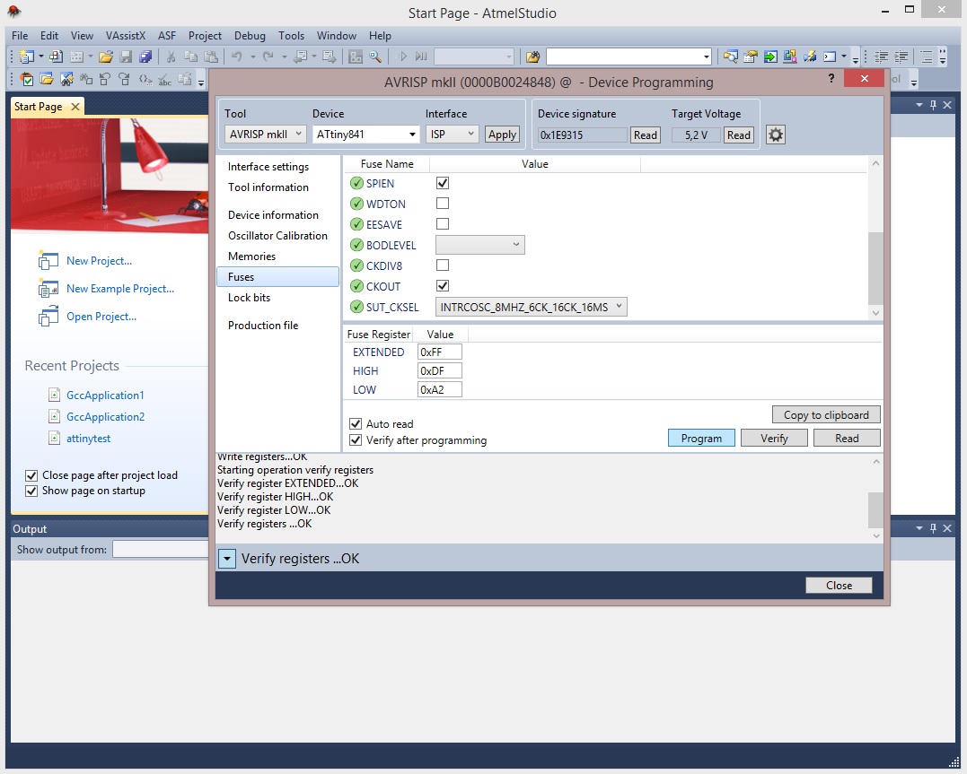
Select the internal oscillator and check the fuse CKOUT option, CKOUT configures the microcontroller to divert the generated signal clock to one of the input/output pins. For this example we have chosen CKOUT because we want to measure the result for a quick analysis.
Internal oscillator. Clock signal through pin B2
If we probe pin B2 with an oscilloscope we could have an idea of how the signal generated by the microcontroller internal oscillator looks like.

Clock signal generated by the internal oscillator at 8.33 MHz
First aspect to note is that the frequency measure is 8.33 Mhz instead of the expected 8 Mhz. That is one of the disadvantages of using the internal oscillator, the microcontroller will lack of a precise signal clock, consequently for example we had to compute some calculation involving timing very precisely then the existing error created by the internal oscillator could spoil the result. Moreover, the internal oscillator is very sensitive to variations of external temperature, there will be changes in frequency subjected to temperature alterations.
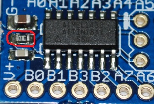
The solution to have a precise clock signal is to use an external crystal with two capacitors for the microcontroller to use it as its clock signal.
External crystal plus capacitors
The picture above provides a visual indication of the external crystal and two capacitors that the microcontroller has to time to execute the different instructions. The crystal is connected to the input/output pins, these pins are dedicated exclusively to the crystal and it should be positioned as near as the designer can to the corresponding pins.
Again to configure the microcontroller to use an external crystal in the fuse configuration window, select EXTOSC_8MHz as shown in the image.
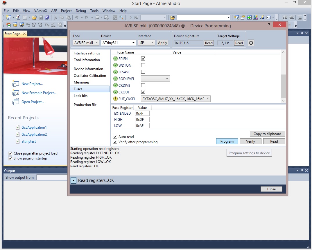
External crystal selection to generate the clock signal
The board has been populated with a 16 Mhz crystal to use it as a clock source, if now we grab the scope again and probe B2, that is outputting the microcontroller clock signal we should see the following signal.

Clock signal generated by the microcontroller with a 16 MHz external crystal
In this case the frequency measurement is spot on, right on 16 MHz, and now its tolerance relative to ambient temperature will be decreased compared to choosing the internal oscillator. Therefore, if our application requires precise timing the way to go is with an external crystal and the two appropriate capacitors (more about it at the related links section).
The main disadvantage of deciding on having an external crystal, other than an extra cost, is the fact that we will have 2 general input/output pins at our disposal.
On the other hand, the advantage other than a better precision in the oscillations is that a greater value crystal could be fitted, 16 MHz is the highest recommended value for the ATtiny841 at 5Vdc, that way the microcontroller can execute instructions faster. We have greater freedom to choose a suitable frequency, that could be fundamental if we had an asynchronous communication and the microcontroller requires a certain frequency to minimize the inherent communication error.
The maximum admissible frequency that the microcontroller can work at is a function of the supply voltage.
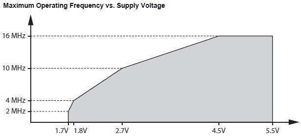
Maximum frequency of the external clock vs supply voltage. ATtiny841
A greater frequency implies a higher current to consume by the microcontroller.
If the aim is to program an application that isn’t really time critical, then the use of an internal oscillator could be appropriate, with that decision we could save on an additional cost and have two extra input/output pins available.
4. Pull-up/Pull-down resistors and other components.
There are specific microcontroller pins that might require either a pull-up or pull-down resistor to function, or to activate a microcontroller feature when it starts up (trigger a bootloader, etc.).
It is common to add an external resistor for the reset pin as the capture below depicts.
Pull-up resistor for the reset pin
The purpose of the reset pin is to reinitiate the microcontroller code and content of a few of its registers. If we are intending to make use of the reset functionality we must place a pull-up resistor to ensure a voltage level state (better than selecting the internal pull-up resistor instead), that not being the case the reset pin will be floating with an unknown voltage state, either high or low, if the latter the microcontroller would be rebooting endlessly.
If there is a lot of noise in the supply lines it is common to place a capacitor between the reset pin and ground. Similar to the digital supply for the microcontroller, the analog part would benefit from adding a coil and capacitor to filter out any noise in the analog side.
Lastly, we would have to add the connectors to complete the hardware interface so that the microcontroller can communicate with the external world, and carry out fascinating computations in our electronic circuit.
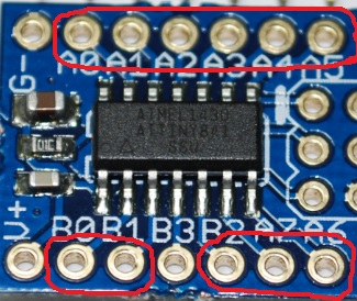
Connectors for the microcontroller general input/output pins
This has been a brief overview of the components that are very common for an electronic design with microcontrollers. All the information relative to the microcontroller design and the components required to get it to operate is in the vendor’s datasheet.
Given all these considerations, if we are learning a new microcontroller family or architecture for the first time, the best thing is to purchase an evaluation board with that target chip, prior to commence any hardware design and/or microcontroller programming expertise. That way we wouldn’t need to worry about any hardware design issues, someone has thought it through, and we can focus on the software, having won half of the battle.
Related links: